Outline Shader
>> using Unity engine 2018.3
50 minutes to complete
You will learn to write a screen space shader to draw outlines around objects. This shader will be integrated with Unity's post-processing stack.
Outline, or edge detection effects are most commonly associated and paired with toon style shading. However, outline shaders have a wide variety of uses, from highlighting important objects on screen to increasing visual clarity in CAD rendering.
This tutorial will describe step-by-step how to write an outline shader in Unity. The shader will be written as a custom effect for Unity's post-processing stack, but the code can also be used in a regular image effect. Concepts introduced here can be found in the Recolor effect from the Kino repository by keijiro, a Unity project that contains a variety of custom effects for the post-processing stack.
Prerequisites
To complete this tutorial, you will need a working knowledge of Unity engine, and an intermediate knowledge of shaders.
Download starter projectThese tutorials are made possible, and kept free and open source, by your support. If you enjoy them, please consider becoming my patron through Patreon.
Become a patronGetting started
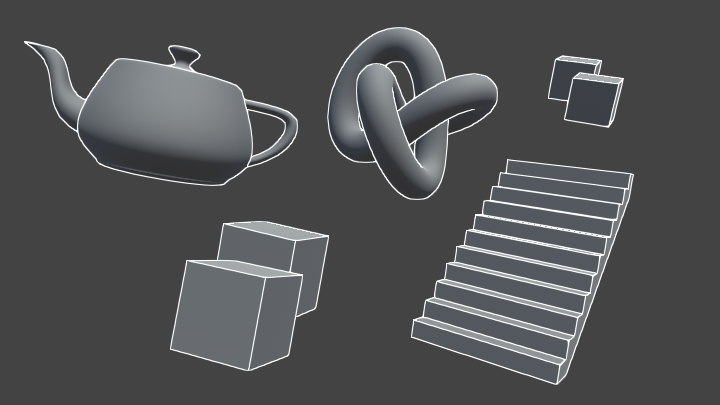
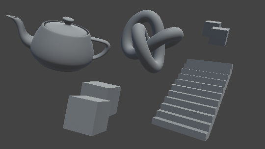
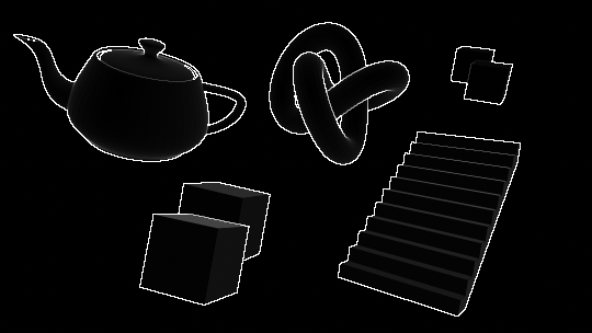
Download the starter project provided above, open it in the Unity editor and open the Main scene. In this scene are several objects, each with a different shape and silhouette. This gives us a variety of surface types to test our outline shader on.
If you select the Main Camera, you will note that already attached to it are the Post Process Layer and Post Process Volume components. These components allow us to make use of the post-processing stack. Assigned to the Profile field of the volume is a post-process profile, OutlinePostProfile. This will contain data that we will use to configure our outline effect.
Note that by default Anti-aliasing in the layer is set to No Anti-aliasing. It can useful to keep anti-aliasing disabled when developing screen space shaders, as it allows you to see the end product of the shader without any further modification applied. For the "finished" screenshots in this tutorial, and for best results, anti-aliasing is set to Subpixel Morphological Anti-aliasing (SMAA) at High quality.
Writing custom post-process effects
Open the Outline shader in your preferred code editor. Shaders written for Unity's post-processing stack have a few differences compared to standard image effects. Although the shader code itself is the same, it is encapsulated in HLSLPROGRAM blocks, instead of CGPROGRAM. As well, some functionality, such as texture sampling, is now handled by macros.
Currently, the Outline file contains a simple fragment shader (named Frag) that samples the image on-screen and returns it without modification. There is also a function named alphaBlend defined; we will use it later for blending our outlines with the on-screen image.
1. Drawing outlines with depth
To generate outlines, we will sample adjacent pixels and compare their values. If the values are very different, we will draw an edge. Some edge detection algorithms work with grayscale images; because we are operating on computer rendered images and not photographs, we have better alternatives in the depth and normals buffers. We will start by using the depth buffer.
We will sample pixels from the depth buffer in a X shape, roughly centred around the current pixel being rendered. Add the following code to the top of the fragment shader.
float halfScaleFloor = floor(_Scale * 0.5);
float halfScaleCeil = ceil(_Scale * 0.5);

float2 bottomLeftUV = i.texcoord - float2(_MainTex_TexelSize.x, _MainTex_TexelSize.y) * halfScaleFloor;
float2 topRightUV = i.texcoord + float2(_MainTex_TexelSize.x, _MainTex_TexelSize.y) * halfScaleCeil;
float2 bottomRightUV = i.texcoord + float2(_MainTex_TexelSize.x * halfScaleCeil, -_MainTex_TexelSize.y * halfScaleFloor);
float2 topLeftUV = i.texcoord + float2(-_MainTex_TexelSize.x * halfScaleFloor, _MainTex_TexelSize.y * halfScaleCeil);
We first calculate two values, halfScaleFloor and halfScaleCeil. These two values will alternatively increment by one as _Scale increases. By scaling our UVs this way, we are able to increment our edge width exactly one pixel at a time—achieving a maximum possible granularity—while still keeping the coordinates centred around i.texcoord.
Next, _Scale will need to be added as a configurable property. Properties are created a bit differently with the post-processing stack. We will first define it as float is our shader program, as usual. Add the following code below the float4 _MainTex_TexelSize line.
float _Scale;Next, open the PostProcessOutline.cs file. This file contains classes that manage rendering our custom effect and exposing any configurable values to the editor. We will expose _Scale as a parameter, and pass it into our shader.
// Add to the PostProcessOutline class.
public IntParameter scale = new IntParameter { value = 1 };

…

// Add to the Render method in the PostProcessOutlineRenderer class, just below var sheet declaration.
sheet.properties.SetFloat("_Scale", settings.scale);
If you select the OutlinePostProfile asset now, you will see that Scale has been exposed to the inspector. We'll leave it at 1 for now.
We are now ready to sample the depth texture using our four UV coordinates.
// Add to the fragment shader, just below float2 topLeftUV.
float depth0 = SAMPLE_DEPTH_TEXTURE(_CameraDepthTexture, sampler_CameraDepthTexture, bottomLeftUV).r;
float depth1 = SAMPLE_DEPTH_TEXTURE(_CameraDepthTexture, sampler_CameraDepthTexture, topRightUV).r;
float depth2 = SAMPLE_DEPTH_TEXTURE(_CameraDepthTexture, sampler_CameraDepthTexture, bottomRightUV).r;
float depth3 = SAMPLE_DEPTH_TEXTURE(_CameraDepthTexture, sampler_CameraDepthTexture, topLeftUV).r;
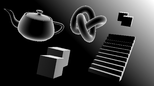
return depth0;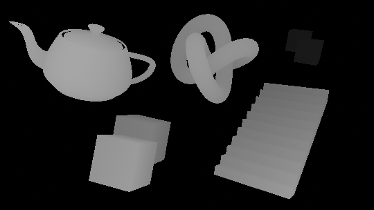
As previously stated, effects integrated with the post-processing stack use a variety of macros to ensure multi-platform compatibility. Here we use SAMPLE_DEPTH_TEXTURE on the camera's depth texture. We only take the r channel, as depth is a scalar value, in the 0...1 range. Note that depth is non-linear; as distance from the camera increases, smaller depth values represent greater distances.
With our values sampled, we can now compare the depth of pixels across from each other through subtraction. Note that existing code that is modified will be highlighted in yellow. New code is not highlighted.
// Add above the return depth0 line. float depthFiniteDifference0 = depth1 - depth0; float depthFiniteDifference1 = depth3 - depth2; … // Replace the existing return depth0 line.return abs(depthFiniteDifference0) * 100;
As the difference can be positive or negative, we take the absolute value of it before returning the result. Since the difference between nearby depth values can be very small (and therefore difficult to see on screen), we multiply the difference by 100 to make it easier to see.
depthFiniteDifference0 is half of the detected edges, while depthFiniteDifference1 is the other half. You can switch the return value between the two to see the difference.
We now have two scalar values representing the intensity of detected outlines in our image; they will now need to be combined into one. There are several trivial ways to do this, from simply adding the two values together, to plugging them into the max function. We will compute the sum of squares of the two values; this is part of an edge detection operator called the Roberts cross.
The Roberts cross involves taking the difference of diagonally adjacent pixels (we have already done this), and computing the sum of squares of the two values. To do this, we will square both our values, add them together, and then square root the result.
// Add below the lines computing the finite differences. float edgeDepth = sqrt(pow(depthFiniteDifference0, 2) + pow(depthFiniteDifference1, 2)) * 100; // Replace the abs(depthFiniteDifference0) * 100 line.return edgeDepth;
You will notice that while the edges come in very clear, there's a lot of dark grey areas along the surfaces of our objects. We will elimate these by thresholding edgeDepth. Add the following code to the shader file...
// Add below the line declaring edgeDepth.
edgeDepth = edgeDepth > _DepthThreshold ? 1 : 0;

…

// Add as a new variable.
float _DepthThreshold;
...and add the code below to PostProcessOutline.cs.
// Add to the PostProcessOutline class.
public FloatParameter depthThreshold = new FloatParameter { value = 0.2f };

…

// Add below the line setting _Scale.
sheet.properties.SetFloat("_DepthThreshold", settings.depthThreshold);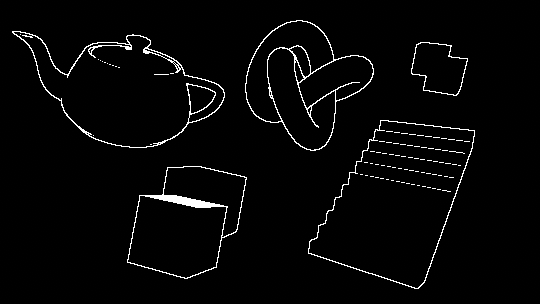
While this has eliminated the dark greys, it has created a few issues. The top of one of the foreground cubes is filled in white, instead of just the edges. As well, the cubes in the background have no edges drawn between their silhouettes. We'll fix the problem with the background cubes for now, and will resolve the foreground one later.
Edges are drawn between areas where the edgeDepth is greater than _DepthThreshold, a constant. It was stated earlier that the depth buffer is non-linear, which has implications for our thresholding. Two cubes a meter apart that are near the camera will have a much larger edgeDepth between them than two cubes that are very far from the camera.
To accommodate this, we will modulate _DepthThreshold based on the existing depth of our surfaces.
// Add below the line declaring edgeDepth. float depthThreshold = _DepthThreshold * depth0; edgeDepth = edgeDepth >depthThreshold? 1 : 0;
_DepthThreshold is now too small for our new equation; set its value to 1.5 for better results.
This has resolved the issue with the background cubes, but also has created more surface artifacts. As well, many edges (such as those along the staircase) were not detected, as the edgeDepth values between steps was too small. To correctly draw outlines on these surfaces, we will make use of the normals buffer.
2. Drawing outlines with normals
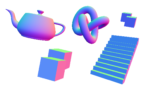
We will now repeat the previous process, except this time using the normals buffer instead of depth. At the end, we will combine the results of the two for maximum edge coverage. Add the following to the fragment shader, below the code sampling the depth buffer.
float3 normal0 = SAMPLE_TEXTURE2D(_CameraNormalsTexture, sampler_CameraNormalsTexture, bottomLeftUV).rgb;
float3 normal1 = SAMPLE_TEXTURE2D(_CameraNormalsTexture, sampler_CameraNormalsTexture, topRightUV).rgb;
float3 normal2 = SAMPLE_TEXTURE2D(_CameraNormalsTexture, sampler_CameraNormalsTexture, bottomRightUV).rgb;
float3 normal3 = SAMPLE_TEXTURE2D(_CameraNormalsTexture, sampler_CameraNormalsTexture, topLeftUV).rgb;
Attached to the camera is a script called RenderReplacementShaderToTexture, setup to generate a camera to render the view-space normals of the scene into _CameraNormalsTexture. We will once again take the difference between these samples to detect outlines.
Note that going forward, you will need to run the scene to get the correct results, as the camera that renders out the normals is generated at runtime.
// Add below the code sampling the normals.
float3 normalFiniteDifference0 = normal1 - normal0;
float3 normalFiniteDifference1 = normal3 - normal2;

float edgeNormal = sqrt(dot(normalFiniteDifference0, normalFiniteDifference0) + dot(normalFiniteDifference1, normalFiniteDifference1));
edgeNormal = edgeNormal > _NormalThreshold ? 1 : 0;

return edgeNormal;

…

// Add as a new variable.
float _NormalThreshold;
The above process is very similar to what we did with depth, with some differences in how we compute the edge. As our normalFiniteDifference values are vectors, and not scalars, we need to transform them from a 3-dimensional value to a single dimensional value before computing the edge intensity. The dot product is ideal for this; not only does it return a scalar, but by performing the dot product for each normalFiniteDifference on itself, we are also squaring the value.
Because we added _NormalThreshold as a new variable, we will need to expose it in PostProcessOutline.cs.
// Add to the PostProcessOutline class.
[Range(0, 1)]
public FloatParameter normalThreshold = new FloatParameter { value = 0.4f };

…

// Add to the Render method in the PostProcessOutlineRenderer class.
sheet.properties.SetFloat("_NormalThreshold", settings.normalThreshold);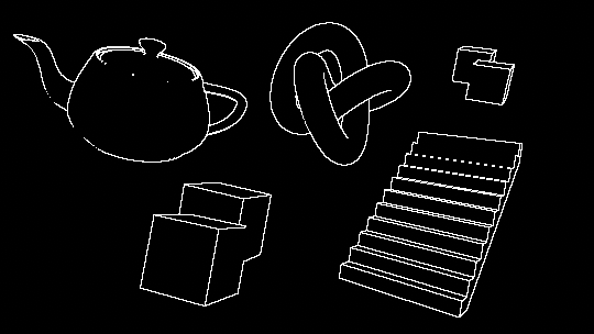
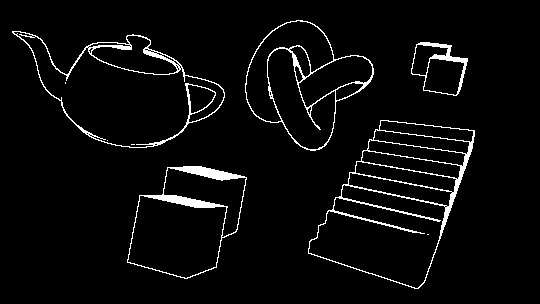
Some new edges, notably those along the staircase's steps, are now visible, while some edges that were previously visible no longer are. To resolve this, we will combine the results of the depth and normal edge detection operations using the max function.
// Remove the return calls we were using for debugging.return edgeNormal;…return edgeDepth;… // Add at the bottom, just above the line declaring float4 color. float edge = max(edgeDepth, edgeNormal); return edge;
3. Resolving surface artifacts
There are a number of artifacts visible on some of the surfaces that lie at sharp angles with respect to the camera. The greater the slope of a surface, the greater the difference between the depth of adjacent pixels. This large depth delta along these surfaces is causing our algorithm to detect "edges" on them.
One option to remove these artifacts is to simply increase _DepthThreshold. While setting it to a value of 6 removes the artifacts entirely, it also is too large a threshold for some outlines that should be detected, like the teapot's rim or some staircase steps.
Instead, we will modulate depthThreshold by the surface's normal. Surfaces that are at a greater angle from the camera with have a larger threshold, while surface that are flatter, or more planar to the camera will have a lower threshold.
To implement this we will need the normal of each surface, and the direction from the camera to the surface (the view direction). We already have the normal, but we don't have access to the view direction.
3.1 Calculating view direction
The normals we sampled from _CameraNormalsTexture are in view space; since these are what we want to compare against, we will need the camera's view direction to also be in view space. As we are working with a screen space shader, the view direction in clip space can be easily calculated from the vertex position. To convert this to view space, we'll need access to the camera's clip to view, or inverse projection matrix.
This matrix is not available by default to screen space shaders; we will calculate it in our C# script and pass it into our shader from there. Add the following just above the line calling BlitFullscreenTriangle...
Matrix4x4 clipToView = GL.GetGPUProjectionMatrix(context.camera.projectionMatrix, true).inverse;
sheet.properties.SetMatrix("_ClipToView", clipToView);
...and add the code below as variables to our shader.
float4x4 _ClipToView;The view to clip (called the projection matrix here) is exposed in the Camera class. Note that we take the inverse of the matrix, as we are transforming our direction from clip to view space, not the other way around. Due to platform differences, it is important to plug the projection matrix into the GetGPUProjectionMatrix function. This ensures that the resulting matrix is correctly configured for our shader.
We can now calculate the view direction in view space. This operation will need to be done in the vertex shader. Up until now, we have been using the built-in VertDefault as our vertex shader. The source code for this shader is available in StdLib.hlsl, which we have included in our file. We'll copy this shader over, and then make some modifications.
// Replace VertDefault with our new shader. #pragma vertexVert… // Add below the alphaBlend function. struct Varyings { float4 vertex : SV_POSITION; float2 texcoord : TEXCOORD0; float2 texcoordStereo : TEXCOORD1; #if STEREO_INSTANCING_ENABLED uint stereoTargetEyeIndex : SV_RenderTargetArrayIndex; #endif }; Varyings Vert(AttributesDefault v) { Varyings o; o.vertex = float4(v.vertex.xy, 0.0, 1.0); o.texcoord = TransformTriangleVertexToUV(v.vertex.xy); #if UNITY_UV_STARTS_AT_TOP o.texcoord = o.texcoord * float2(1.0, -1.0) + float2(0.0, 1.0); #endif o.texcoordStereo = TransformStereoScreenSpaceTex(o.texcoord, 1.0); return o; } … // Update the fragment shader's declaration to take in our new Varyings struct, instead of VaryingsDefault. float4 Frag(Varyingsi) : SV_Target
In addition to copying over the vertex shader, we have also copied the default struct that is passed from the vertex shader, Varyings. This will allow us to pass the view direction to our fragment shader.
The clip space position (which ranges from -1, -1 at the top left of the screen to 1, 1 at the bottom right) can be interpreted as a the camera's view direction to each pixel, in clip space. This position is already calculated and stored in o.vertex. We will multiply this value by our matrix to transform the direction to view space.
// Add to the vertex shader, below the line assigning o.vertex.
o.viewSpaceDir = mul(_ClipToView, o.vertex).xyz;

…

// Add to the Varyings struct.
float3 viewSpaceDir : TEXCOORD2;
You can debug this value out by adding the following to the top of our fragment shader.
return float4(i.viewSpaceDir, 1);Make sure to remove this line of code after you have observed its results, as we will not use it any further.
3.2 Thresholding with view direction
We are going to modulate depthThreshold based on the difference between the camera's viewing normal and the normal of the surface. To achieve this, we will use the dot product. Add the following below the line declaring edgeDepth.
float3 viewNormal = normal0 * 2 - 1;
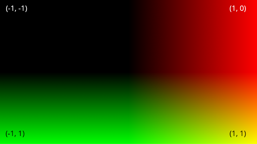
float NdotV = 1 - dot(viewNormal, -i.viewSpaceDir);
return NdotV;When the view normal is sampled from _CameraNormalsTexture it is the range 0...1, while i.viewSpaceDir is in the -1...1 range. We transform the view normal so that both normals are in the same range, and then take the dot product between the two.
As the angle between the normal and the camera increases, the result of the dot product gets larger (as we have inverted it). We want depthThreshold to get larger as the angle increases, too. We could just multiply it by NdotV, but we'll manipulate the value a bit beforehand to gain more control. We will construct a variable called normalThreshold, and multiply depthThreshold by it.
Currently, NdotV ranges from -1...1. We are going to first rescale the value to the 0...1 range to make it easier to work with. We will add a lower bound cutoff, since it is unnecessary to modify the threshold of surfaces that are mostly facing the camera.
// Add below the line declaring NdotV.
float normalThreshold01 = saturate((NdotV - _DepthNormalThreshold) / (1 - _DepthNormalThreshold));
The above equation takes all values of NdotV in the range from _DepthNormalThreshold to 1, and rescales them to be 0...1. By having a lower bound in this way, we are able to apply our new threshold only when surfaces are above a certain angle from the camera. This equation is exposed in Unity as Mathf.InverseLerp, where a is _DepthNormalThreshold, b is 1, and value is NdotV.
Before we multiply it into depthThreshold, we want to do one final transformation of the range. We will take it from 0...1 to instead be from 1 to an upper bound we will define as _DepthNormalThresholdScale.
// Add below the line declaring normalThreshold01.
float normalThreshold = normalThreshold01 * _DepthNormalThresholdScale + 1;
With that done, we can multiply in our value and expose our new variables to the inspector.
// Modify the existing line declaring depthThreshold. float depthThreshold = _DepthThreshold * depth0* normalThreshold; … // Add as new variables. float _DepthNormalThreshold; float _DepthNormalThresholdScale; … // Remove the debug return call.return NdotV;
// Add to PostProcessOutlineRenderer.
[Range(0, 1)]
public FloatParameter depthNormalThreshold = new FloatParameter { value = 0.5f };
public FloatParameter depthNormalThresholdScale = new FloatParameter { value = 7 };

…

// Add to PostProcessOutlineRenderer.
sheet.properties.SetFloat("_DepthNormalThreshold", settings.depthNormalThreshold);
sheet.properties.SetFloat("_DepthNormalThresholdScale", settings.depthNormalThresholdScale);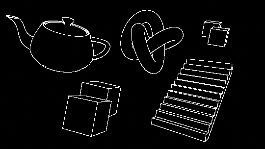
4. Final composition
With our outlines looking nice and clean, we can now blend them together with the scene. Before doing so, we'll add a new property to control the color of the outlines.
// Add just above the line declaring float4 color.
float4 edgeColor = float4(_Color.rgb, _Color.a * edge);

…

// Add as a new variable.
float4 _Color;
// Add to PostProcessOutlineRenderer.
public ColorParameter color = new ColorParameter { value = Color.white };
…
// Add to PostProcessOutlineRenderer.
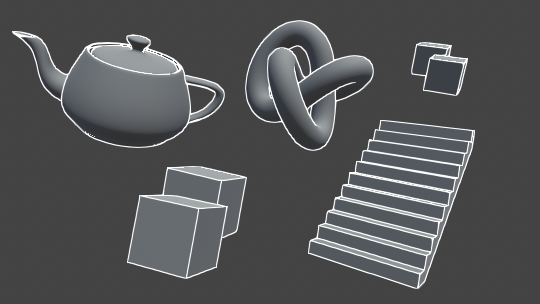
sheet.properties.SetColor("_Color", settings.color);Lastly, we'll blend the color sampled from the scene with the outlines, using the alphaBlend function.
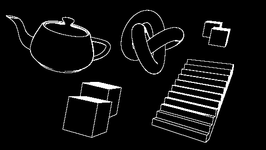
// Remove the debug return call.return edge;… // Replace the existing return color line, at the very end of the fragment shader.return alphaBlend(edgeColor, color);
Conclusion
This shader can be used to generate a wide variety of effects and styles. Disabling anti-aliasing and pairing with a dither overlay can output a retro look similar to Return of the Obra Dinn. Adding variable edge thickness via dilation can create strokes reminiscent of 2D illustration, as described in this paper by Pixar.
View sourceLeave me a message
You can contact me about this article at Copied to clipboardroystanhonks@gmail.com 📋 roystanhonks@gmail.com 📧 . Sometimes I receive a lot of messages, but I'll try and get back to you as soon as I can!