Grass Shader
>> using Unity engine 2018.3
60 minutes to complete
You will learn to write a geometry shader to generate blades of grass from an input mesh's vertices, and use tessellation to control the density of the grass.
This tutorial will describe step-by-step how to write a grass shader for Unity. The shader will take an input mesh, and from each vertex on the mesh generate a blade of grass using a geometry shader. To create interest and realism, the blades will have randomized dimensions and rotations, and be affected by wind. To control the density of the grass, tessellation will be used to subdivide the input mesh. The grass will be capable of both casting and receiving shadows.
Prerequisites
To complete this tutorial, you will need a working knowledge of Unity engine, and an intermediate understanding of shader syntax and functionality.
Download starter projectThese tutorials are made possible, and kept free and open source, by your support. If you enjoy them, please consider becoming my patron through Patreon.
Become a patronGetting started
Download the starter project provided above and open it in the Unity editor. Open the Main scene, and open the Grass shader in your preferred code editor.
This file contains a shader that outputs the color white, along with some functions we will use throughout this tutorial. You'll notice that these functions, along with the vertex shader, are enclosed in a CGINCLUDE block placed outside the SubShader. Code placed in this block will be automatically included in any passes in the shader; this will be useful later, as our shader will have multiple passes.
We will begin by writing a geometry shader to generate triangles from each vertex on our mesh's surface.
1. Geometry shaders
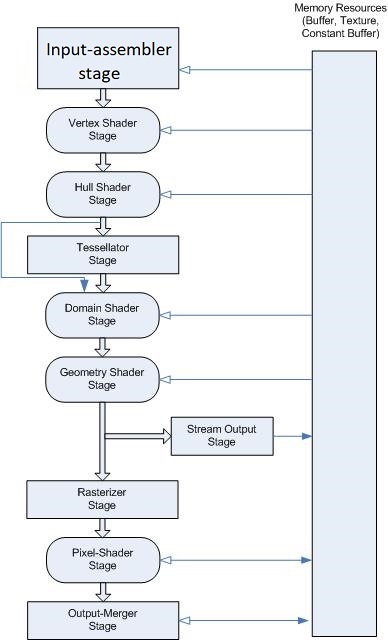
Geometry shaders are an optional part of the rendering pipeline. They are executed after the vertex shader (or the tessellation shader—if tessellation is being used), and before the vertices are processed for the fragment shader.
Geometry shaders take in a single primitive as input, and can generate zero, one, or many primitives. We will start by writing a geometry shader to take in a vertex (or point) as input, and output a single triangle to represent a blade of grass.
// Add inside the CGINCLUDE block.
struct geometryOutput
{
	float4 pos : SV_POSITION;
};

[maxvertexcount(3)]
void geo(triangle float4 IN[3] : SV_POSITION, inout TriangleStream<geometryOutput> triStream)
{
}

…

// Add inside the SubShader Pass, just below the #pragma fragment frag line.
#pragma geometry geo
The above declares a geometry shader named geo, with two parameters. The first, triangle float4 IN[3], states that we will take in a single triangle (composed of three points) as our input. The second, of type TriangleStream, sets up our shader to output a stream of triangles, with each vertex using the geometryOutput structure to carry its data.
In addition, we add a final parameter above the function declaration in square brackets: [maxvertexcount(3)]. This tells the GPU that we will emit (but are not required to) at most 3 vertices. We also make sure that our SubShader uses the geometry shader, by declaring it inside the Pass.
Our geometry shader doesn't yet do anything; add the following code inside the geometry shader to emit a triangle.
geometryOutput o;

o.pos = float4(0.5, 0, 0, 1);
triStream.Append(o);

o.pos = float4(-0.5, 0, 0, 1);
triStream.Append(o);

o.pos = float4(0, 1, 0, 1);
triStream.Append(o);
This has yielded some odd results. Panning the camera around reveals that the triangle is being rendered in screen space. This makes sense; since the geometry shader occurs immediately before vertex processing, it takes over responsibility from the vertex shader to ensure vertices are outputted in clip space. We'll modify our code to reflect this.
// Update the return call in the vertex shader.return UnityObjectToClipPos(vertex);return vertex; … // Update each assignment of o.pos in the geometry shader. o.pos =UnityObjectToClipPos(float4(0.5, 0, 0, 1));… o.pos =UnityObjectToClipPos(float4(-0.5, 0, 0, 1));… o.pos =UnityObjectToClipPos(float4(0, 1, 0, 1));
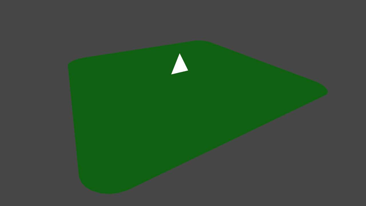
Our triangle is now correctly rendered in the world. However, it appears that only one is being created. In actuality, a triangle is being drawn for each vertex in our mesh, but the positions we are assigning to the triangle's vertices are constant—they do not change for each input vertex— placing all the triangles atop one another.
We will correct this by updating our output vertex positions to be offsets from the input point.
// Add to the top of the geometry shader. float3 pos = IN[0]; … // Update each assignment of o.pos. o.pos = UnityObjectToClipPos(pos +float3(0.5, 0, 0)); … o.pos = UnityObjectToClipPos(pos +float3(-0.5, 0, 0)); … o.pos = UnityObjectToClipPos(pos +float3(0, 1, 0));
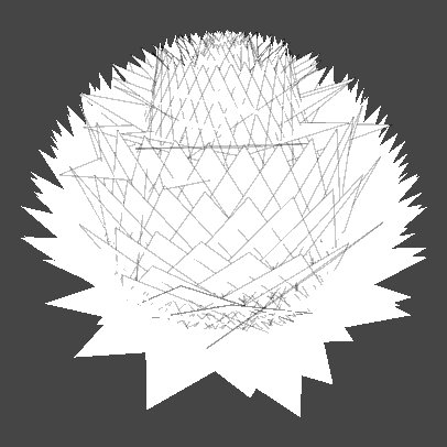
Triangles are now correctly drawn with their base positioned at their emitting vertex. Before moving on, set the GrassPlane object inactive in the scene, and set the GrassBall object active. As we want our grass to be generated correctly for all kinds of surfaces, it is important to test it on different shaped meshes.

Right now, the triangles are all being emitted in the same direction, rather than outwards from the surface of the sphere. To resolve this, we will construct our grass blades in tangent space.
2. Tangent space
Ideally, we want to build our blades of grass—applying random widths, heights, curvature, rotation—without having to consider the angle of the surface the blade is being emitted from. In simpler terms, we will define the blade in space local to the vertex emitting it, and then transform it to be local to the mesh. This space is called tangent space.

Like any kind of space, we can define the tangent space of our vertex with three vectors: a right, forward, and up. With these vectors, we can construct a matrix to rotate our blade of grass from tangent to local space.
We can access a right and up vector by adding some new vertex inputs.
// Add to the CGINCLUDE block. struct vertexInput { float4 vertex : POSITION; float3 normal : NORMAL; float4 tangent : TANGENT; }; struct vertexOutput { float4 vertex : SV_POSITION; float3 normal : NORMAL; float4 tangent : TANGENT; }; … // Modify the vertex shader.vertexOutput vert(vertexInput v) { vertexOutput o; o.vertex = v.vertex; o.normal = v.normal; o.tangent = v.tangent; return o; }… // Modify the input for the geometry shader. Note that the SV_POSITION semantic is removed. void geo(trianglevertexOutput IN[3], inout TriangleStream<geometryOutput> triStream) … // Modify the existing line declaring pos. float3 pos = IN[0].vertex;
A third vector can be calculated by taking the cross product between the other two vectors. The cross product returns a vector perpendicular to its two input vectors.
// Place in the geometry shader, below the line declaring float3 pos.
float3 vNormal = IN[0].normal;
float4 vTangent = IN[0].tangent;
float3 vBinormal = cross(vNormal, vTangent) * vTangent.w;With all three vectors, we can construct a matrix to transform between tangent and local space. We will multiply each vertex in our blade of grass by this matrix before it is passed into UnityObjectToClipPos, which expects a vertex in local space.
// Add below the lines declaring the three vectors.
float3x3 tangentToLocal = float3x3(
	vTangent.x, vBinormal.x, vNormal.x,
	vTangent.y, vBinormal.y, vNormal.y,
	vTangent.z, vBinormal.z, vNormal.z
	);
Before using this matrix, we'll move our vertex output code into a function to avoiding writing the same lines of code over and over again. This is often called the DRY principle, or don't repeat yourself.
// Add to the CGINCLUDE block. geometryOutput VertexOutput(float3 pos) { geometryOutput o; o.pos = UnityObjectToClipPos(pos); return o; } … // Remove the following from the geometry shader.geometryOutput o; o.pos = UnityObjectToClipPos(pos + float3(0.5, 0, 0)); triStream.Append(o); o.pos = UnityObjectToClipPos(pos + float3(-0.5, 0, 0)); triStream.Append(o); o.pos = UnityObjectToClipPos(pos + float3(0, 1, 0)); triStream.Append(o);// ...and replace it with the code below. triStream.Append(VertexOutput(pos + float3(0.5, 0, 0))); triStream.Append(VertexOutput(pos + float3(-0.5, 0, 0))); triStream.Append(VertexOutput(pos + float3(0, 1, 0)));
Finally, we will multiply out output vertices by the tangentToLocal matrix, correctly aligning them with their input point's normal.
triStream.Append(VertexOutput(pos +mul(tangentToLocal, float3(0.5, 0, 0)))); triStream.Append(VertexOutput(pos +mul(tangentToLocal, float3(-0.5, 0, 0)))); triStream.Append(VertexOutput(pos +mul(tangentToLocal, float3(0, 1, 0))));
This looks closer to what we want, but is not entirely correct. The issue here is that we initially defined our "up" direction to be on the Y axis; in tangent space, however, convention usually dictates the up direction be along the Z axis. We'll make that change now.
// Modify the position of the third vertex being emitted.
triStream.Append(VertexOutput(pos + mul(tangentToLocal, float3(0, 0, 1))));

3. Grass look
To make our triangles look more like blades of grass, we'll need to add some color and variety. We will start by adding a gradient that runs from the top of the blade to the bottom.
3.1 Color gradient
Our goal is to allow the artist to define two colors—a top and a bottom—and interpolate between these two colors from the tip of the blade to the base. These colors are already defined in the shader file as _TopColor and _BottomColor. To sample them correctly, we will need to provide the fragment shader with UV coordinates.
// Add to the geometryOutput struct. float2 uv : TEXCOORD0; … // Modify the VertexOutput function signature. geometryOutput VertexOutput(float3 pos,float2 uv) … // Add to VertexOutput, just below the line assigning o.pos. o.uv = uv; … // Modify the existing lines in the geometry shader. triStream.Append(VertexOutput(pos + mul(tangentToLocal, float3(0.5, 0, 0)),float2(0, 0))); triStream.Append(VertexOutput(pos + mul(tangentToLocal, float3(-0.5, 0, 0)),float2(1, 0))); triStream.Append(VertexOutput(pos + mul(tangentToLocal, float3(0, 0, 1)),float2(0.5, 1)));
We construct the UVs for our blade in a triangle shape, with the two base vertices at the bottom left and right, and the tip vertex placed center-top.

We can now sample our top and bottom colors in the fragment shader using the UV, and interpolate between them using lerp. We'll also need to modify the fragment shader's parameters to take geometryOutput as input, rather just only the float4 position.
// Modify the function signature of the fragment shader. float4 frag (geometryOutput i, fixed facing : VFACE) : SV_Target … // Replace the existing return call.return float4(1, 1, 1, 1);return lerp(_BottomColor, _TopColor, i.uv.y);
3.2 Random facing direction
To create variation and add a more natural look, we'll next make every blade of grass face a random direction. To do this, we'll need to construct a rotation matrix that rotates a random amount around the blade's up axis.
The shader file has two functions included that will help us do this: rand, which generates a random number from a 3-dimensional input, and AngleAxis3x3, which takes an angle (in radians) and returns a matrix rotating that amount around the provided axis. The latter function works the same way as the Quaternion.AngleAxis C# function (although AngleAxis3x3 returns a matrix, not a quaternion).
The rand function returns a number in the 0...1 range; we will multiply this by two Pi to get the full gamut of angular values.
// Add below the line declaring the tangentToLocal matrix.
float3x3 facingRotationMatrix = AngleAxis3x3(rand(pos) * UNITY_TWO_PI, float3(0, 0, 1));
We use the input position pos as the random seed for our rotation. This way, every blade will get a different rotation, but it will be consistent between frames.
The rotation can be applied to the blade by multiplying it with the existing tangentToLocal matrix. Note that matrix multiplication is not commutative; the order of the operands does matter.
// Add below the line declaring facingRotationMatrix.
float3x3 transformationMatrix = mul(tangentToLocal, facingRotationMatrix);

…

// Replace the multiplication matrix operand with our new transformationMatrix.
triStream.Append(VertexOutput(pos + mul(transformationMatrix, float3(0.5, 0, 0)), float2(0, 0)));
triStream.Append(VertexOutput(pos + mul(transformationMatrix, float3(-0.5, 0, 0)), float2(1, 0)));
triStream.Append(VertexOutput(pos + mul(transformationMatrix, float3(0, 0, 1)), float2(0.5, 1)));

3.3 Random forward bend
If the blades of grass all stand up perfectly straight, they look very uniform. This may be desirable for well tended grass, like on a putting green, but does not accurately represent grass in the wild. We'll create a new matrix to rotate the grass along its X axis, and a property to control this rotation.
// Add as a new property.
_BendRotationRandom("Bend Rotation Random", Range(0, 1)) = 0.2

…

// Add to the CGINCLUDE block.
float _BendRotationRandom;

…

// Add to the geometry shader, below the line declaring facingRotationMatrix.
float3x3 bendRotationMatrix = AngleAxis3x3(rand(pos.zzx) * _BendRotationRandom * UNITY_PI * 0.5, float3(-1, 0, 0));
We use the position again as our random seed, this time swizzling it to create a unique seed. We also multiply UNITY_PI by 0.5; this gives us a random range of 0...90 degrees.
Once again, we apply this matrix through rotation, taking care to add it in the correct order.
// Modify the existing line. float3x3 transformationMatrix = mul(mul(tangentToLocal, facingRotationMatrix),bendRotationMatrix);
3.4 Width and height
The grass blades' dimensions right now are fixed at 1 unit wide, 1 unit tall. We will add some properties to control this, as well as some properties to add some random variation.
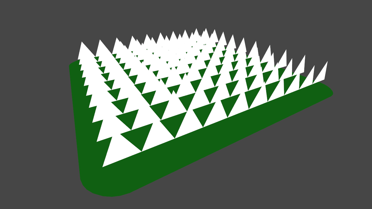
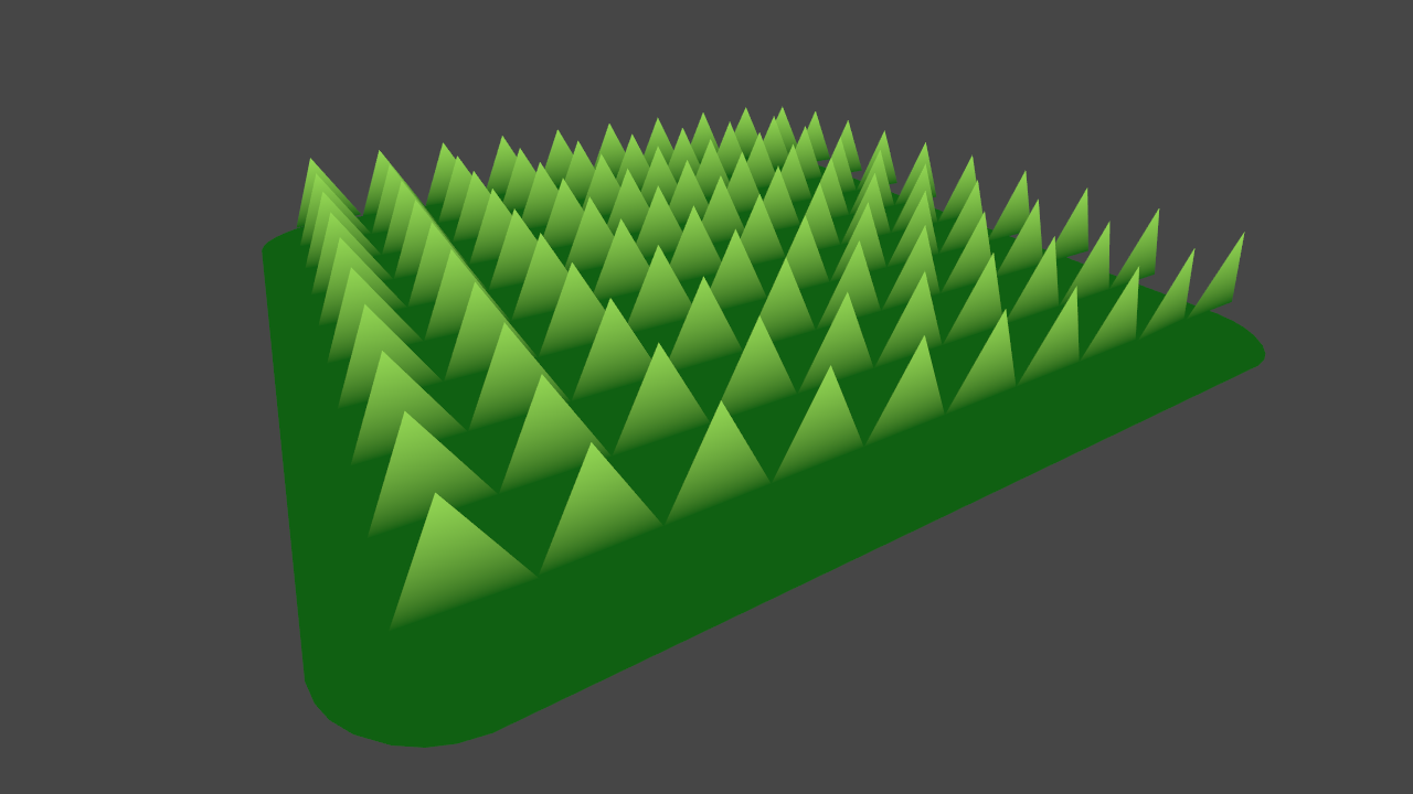
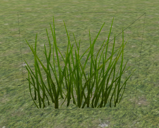
// Add as new properties. _BladeWidth("Blade Width", Float) = 0.05 _BladeWidthRandom("Blade Width Random", Float) = 0.02 _BladeHeight("Blade Height", Float) = 0.5 _BladeHeightRandom("Blade Height Random", Float) = 0.3 … // Add to the CGINCLUDE block. float _BladeHeight; float _BladeHeightRandom; float _BladeWidth; float _BladeWidthRandom; … // Add to the geometry shader, above the triStream.Append calls. float height = (rand(pos.zyx) * 2 - 1) * _BladeHeightRandom + _BladeHeight; float width = (rand(pos.xzy) * 2 - 1) * _BladeWidthRandom + _BladeWidth; … // Modify the existing positions with our new height and width. triStream.Append(VertexOutput(pos + mul(transformationMatrix, float3(width, 0, 0)), float2(0, 0))); triStream.Append(VertexOutput(pos + mul(transformationMatrix, float3(-width, 0, 0)), float2(1, 0))); triStream.Append(VertexOutput(pos + mul(transformationMatrix, float3(0, 0,height)), float2(0.5, 1)));

The triangles now much more closely resemble blades of grass, but—there are far too few of them. There simply are not enough vertices in the input mesh to create the appearance of a dense field.
One solution would be to create a new, denser mesh, either through C# or using 3D modelling software. While this would work, it would not allow for dynamic control of the grass density. Instead, we will subdivide the input mesh using tessellation.
4. Tessellation
Tessellation is an optional stage in the rendering pipeline that occurs after the vertex shader, and before the geometry shader (if there is one). Its job is to subdivide a a single input surface into a many primitives. Tessellation is implemented with two programmable stages: the hull and domain shaders.
For surface shaders, Unity has a built-in tessellation implementation. However, as we are not using surface shaders, it is necessary to implement custom hull and domain shaders. This article will not go into implementing tessellation in detail—instead, we will make use of the included CustomTessellation.cginc file. This file is adapted from this article by Catlike Coding, which is an excellent reference on how to implement tessellation in Unity.
If we enable the TessellationExample object in the scene, we can see it already has a material applied that implements tessellation. Modifying the Tessellation Uniform property will demonstrate the subdivision effect.
We will implement tessellation in our grass shader to control the density of the plane, and therefore control the number of generate blades. First, we need to include the CustomTessellation.cginc file. We will reference it by its relative path to our shader.
// Add inside the CGINCLUDE block, below the other #include statements.
#include "Shaders/CustomTessellation.cginc"
If you open CustomTessellation.cginc, you will note that it has already defined vertexInput and vertexOutput structs, as well as a vertex shader. It is unnecessary to redefine them in our grass shader; they can be removed.
struct vertexInput
{
	float4 vertex : POSITION;
	float3 normal : NORMAL;
	float4 tangent : TANGENT;
};

struct vertexOutput
{
	float4 vertex : SV_POSITION;
	float3 normal : NORMAL;
	float4 tangent : TANGENT;
};

vertexOutput vert(vertexInput v)
{
	vertexOutput o;
	o.vertex = v.vertex;
	o.normal = v.normal;
	o.tangent = v.tangent;
	return o;
}
Note that the vertex shader vert in CustomTessellation.cginc simply passes the input directly through to the tessellation stage; the job of creating the vertexOutput struct is taken care of by the tessVert function, called inside the domain shader.
We can now add the hull and domain shaders to our grass shader. As well, we will add a new property, _TessellationUniform, to control the subdivision amount—the matching variable for this property is already declared in CustomTessellation.cginc.
// Add as a new property.
_TessellationUniform("Tessellation Uniform", Range(1, 64)) = 1
…
// Add below the other #pragma statements in the SubShader Pass.
#pragma hull hull
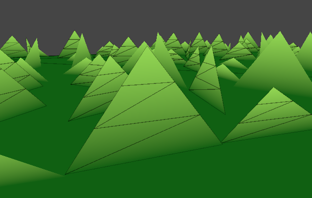
#pragma domain domainModifying the Tessellation Uniform property now allows us to control the grass density. I've found that a value of 5 produces good results.
5. Wind
We will implement wind by sampling a distortion texture. This texture will be similar to a normal map, except with only two channels (red and green) instead of three. We will use these two channels as the X and Y directions of the wind.
Before sampling the wind texture, we will need to construct a UV coordinate. Rather than using texture coordinates assigned to the mesh, we will use the input point's position. This way, if there are multiple grass meshes in the world, this will create the illusion they are all part of the same wind system. As well, we will use the built-in shader variable _Time to scroll the wind texture along our grass surface.
// Add as new properties.
_WindDistortionMap("Wind Distortion Map", 2D) = "white" {}
_WindFrequency("Wind Frequency", Vector) = (0.05, 0.05, 0, 0)

…

// Add to the CGINCLUDE block.
sampler2D _WindDistortionMap;
float4 _WindDistortionMap_ST;

float2 _WindFrequency;

…

// Add to the geometry shader, just above the line declaring the transformationMatrix.
float2 uv = pos.xz * _WindDistortionMap_ST.xy + _WindDistortionMap_ST.zw + _WindFrequency * _Time.y;
We apply the _WindDistortionMap scale and offset to our position, and then further offset it by _Time.y, scaled by _WindFrequency. We'll now use this UV to sample our texture, and create a property to control the wind strength.
// Add as a new property.
_WindStrength("Wind Strength", Float) = 1

…

// Add to the CGINCLUDE block.
float _WindStrength;

…

// Add below the line declaring float2 uv.
float2 windSample = (tex2Dlod(_WindDistortionMap, float4(uv, 0, 0)).xy * 2 - 1) * _WindStrength;
Note that we rescale the sampled value from the texture from a 0...1 range to be in a -1...1 range. Next, we can construct a normalized vector representing the direction of the wind.
// Add below the line declaring float2 windSample.
float3 wind = normalize(float3(windSample.x, windSample.y, 0));
We can now construct a matrix to rotate about this vector, and multiply it into our transformationMatrix.
// Add below the line declaring float3 wind. float3x3 windRotation = AngleAxis3x3(UNITY_PI * windSample, wind); … // Modify the existing line. float3x3 transformationMatrix =mul(mul(mul(tangentToLocal, windRotation), facingRotationMatrix), bendRotationMatrix);
Finally, in the Unity editor, apply the Wind texture (found at the root of the project) to the Wind Distortion Map slot of our grass material. As well, set the Tiling of the texture to 0.01, 0.01.
If the grass isn't animating in the Scene view, click the Toggle skybox, fog, and various other effects button to enable animated materials.
From far away, this looks correct—however, if we inspect the blades of grass up close, we'll notice that the entire blade is rotating, causing the base to no longer be pinned to the ground.
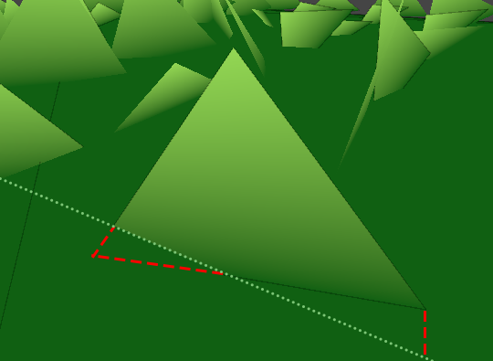
We'll correct this by defining a second transformation matrix that we apply only to the two base vertices. This matrix will not include the windRotation or bendRotationMatrix matrices, ensuring the base of the blade stays attached to its surface.
// Add below the line declaring float3x3 transformationMatrix.
float3x3 transformationMatrixFacing = mul(tangentToLocal, facingRotationMatrix);

…

// Modify the existing lines outputting the base vertex positions.
triStream.Append(VertexOutput(pos + mul(transformationMatrixFacing, float3(width, 0, 0)), float2(0, 0)));
triStream.Append(VertexOutput(pos + mul(transformationMatrixFacing, float3(-width, 0, 0)), float2(1, 0)));
6. Blade curvature
Right now, our individual blades of grass are defined by a single triangle. While this is not a problem at long distances, up close the blades look overly rigid and geometric, rather than organic and alive. We will correct this by instead constructing our blades with several triangles and bending them along a curve.
Each blade of grass will be subdivided into a number of segments. Each segment will be rectangular in shape, and made up of two triangles, excluding the top segment—this will be a single triangle representing the blade's tip.
Up until now, we've only outputted three vertices, making for a single triangle—so with more vertices, how does the geometry shader know which ones should connect to each another to form triangles? The answer lies in the triangle strip data structure. The first three vertices are connected to form a triangle—as before—with each additional vertex forming a triangle with the previous two.

This is not only more memory efficient, but also makes it easy to quickly construct sequences of triangles in code. If we wished to have multiple triangle strips, we could call the RestartStrip function on the TriangleStream.
Before we begin outputting more vertices from our geometry shader, we will need to increase the maxvertexcount. We'll use a #define statement to allow the shader's author to control the number of segments, and calculate the number of outputted vertices from that.
// Add to the CGINCLUDE block.
#define BLADE_SEGMENTS 3

…

// Modify the existing line defining the maxvertexcount.
[maxvertexcount(BLADE_SEGMENTS * 2 + 1)]
We initial define our segment count to be 3, and update our maxvertexcount to calculate the number of vertices based off the segment count.
To create our segmented blade of grass, we will use a for loop. Each iteration of the loop will add two vertices: a left and a right. After the top is complete, we will add a final vertex at the tip of the blade.
Before we do this, it will be useful to move some of our code calculating our grass vertex positions into a function, as we will be using the code several times in and outside our loop. Add the following to the CGINCLUDE block.
geometryOutput GenerateGrassVertex(float3 vertexPosition, float width, float height, float2 uv, float3x3 transformMatrix)
{
	float3 tangentPoint = float3(width, 0, height);

	float3 localPosition = vertexPosition + mul(transformMatrix, tangentPoint);
	return VertexOutput(localPosition, uv);
}
This function carries the same responsibilities as our the arguments we currently pass in to VertexOutput to generate our blade vertices. Taking in a position, width, and height, it correctly transforms the vertex by the provided matrix, and assigns it a UV coordinate. We'll update our existing code with this function to ensure it is properly working.
// Update the existing code outputting the vertices.
triStream.Append(GenerateGrassVertex(pos, width, 0, float2(0, 0), transformationMatrixFacing));
triStream.Append(GenerateGrassVertex(pos, -width, 0, float2(1, 0), transformationMatrixFacing));
triStream.Append(GenerateGrassVertex(pos, 0, height, float2(0.5, 1), transformationMatrix));
With our function working correctly, we are ready to move our vertex generation code into a for loop. Add the following below the line declaring float width.
for (int i = 0; i < BLADE_SEGMENTS; i++)
{
	float t = i / (float)BLADE_SEGMENTS;
}
We declare a loop that will run once for each segment in the blade. Inside the loop, we add the variable t. This variable will hold a value, from 0...1, representing how far we are along the blade. We will use this value to calculate the width and height of the segment in each iteration of the loop, which we can do now.
// Add below the line declaring float t.
float segmentHeight = height * t;
float segmentWidth = width * (1 - t);
As we move up the blade, the height increases, and the width decreases (as it tapers inwards). We can now add GenerateGrassVertex calls to our loop to add the vertices to the triangle stream. We'll also make a single call to GenerateGrassVertex outside of the loop to add the vertex at the tip.
// Add below the line declaring float segmentWidth.
float3x3 transformMatrix = i == 0 ? transformationMatrixFacing : transformationMatrix;

triStream.Append(GenerateGrassVertex(pos, segmentWidth, segmentHeight, float2(0, t), transformMatrix));
triStream.Append(GenerateGrassVertex(pos, -segmentWidth, segmentHeight, float2(1, t), transformMatrix));

…

// Add just below the loop to insert the vertex at the tip of the blade.
triStream.Append(GenerateGrassVertex(pos, 0, height, float2(0.5, 1), transformationMatrix));

…

// Remove the existing calls to triStream.Append.
triStream.Append(GenerateGrassVertex(pos, width, 0, float2(0, 0), transformationMatrixFacing));
triStream.Append(GenerateGrassVertex(pos, -width, 0, float2(1, 0), transformationMatrixFacing));
triStream.Append(GenerateGrassVertex(pos, 0, height, float2(0.5, 1), transformationMatrix));
Note the line declaring float3x3 transformMatrix—here we select between our two transformation matrices, taking transformationMatrixFacing for the vertices at the base, and transformationMatrix for all others.
The blades of grass are now divided into multiple segments, but the surface of the blade is still planar—the newly added triangles are not yet being used. We'll add some curvature to the blade by offsetting the Y position of the vertices. First, we'll need to modify our GenerateGrassVertex function to take in a Y offset we'll call forward.
// Update the function signature of GenerateGrassVertex. geometryOutput GenerateGrassVertex(float3 vertexPosition, float width, float height,float forward, float2 uv, float3x3 transformMatrix) … // Modify the Y coordinate assignment of tangentPoint. float3 tangentPoint = float3(width,forward, height);
To calculate the forward offset of each vertex, we will plug t into the pow function. By taking t to a power, its influence on the forward offset will be non-linear, shaping the blade of grass into a curve.
// Add as new properties. _BladeForward("Blade Forward Amount", Float) = 0.38 _BladeCurve("Blade Curvature Amount", Range(1, 4)) = 2 … // Add to the CGINCLUDE block. float _BladeForward; float _BladeCurve; … // Add inside the geometry shader, below the line declaring float width. float forward = rand(pos.yyz) * _BladeForward; … // Add inside the loop, below the line declaring segmentWidth. float segmentForward = pow(t, _BladeCurve) * forward; … // Modify the GenerateGrassVertex calls inside the loop. triStream.Append(GenerateGrassVertex(pos, segmentWidth, segmentHeight,segmentForward, float2(0, t), transformMatrix)); triStream.Append(GenerateGrassVertex(pos, -segmentWidth, segmentHeight,segmentForward, float2(1, t), transformMatrix)); … // Modify the GenerateGrassVertex calls outside the loop. triStream.Append(GenerateGrassVertex(pos, 0, height,forward, float2(0.5, 1), transformationMatrix));
The above is a large chunk of code, but all of the work done is similar to what was done for the width and height of the blade. Lower values of _BladeForward and _BladeCurve will result in a more organized, well tended field of grass, while larger values will have the opposite effect.

7. Lighting and shadows
As a final step to complete this shader, we will add the ability to cast and receive shadows. We will also add some simple illumination, received from the main directional light.
7.1 Casting shadows
In order to cast shadows in Unity, a second pass must be added to the shader. This pass will be used by shadow casting lights in the scene to render the grass's depth to their shadow map. This means our geometry shader will need to also run in the shadow pass to ensure the grass blades exist to cast shadows.
Since our geometry shader is written inside CGINCLUDE blocks, it is available for us to use in any passes in the file. We'll create a second pass that will make use of all of the same shaders as our initial pass, with the exception of the fragment shader—we'll define a new one that is populated with a macro that handles the output for us.
// Add below the existing Pass.
Pass
{
	Tags
	{
		"LightMode" = "ShadowCaster"
	}

	CGPROGRAM
	#pragma vertex vert
	#pragma geometry geo
	#pragma fragment frag
	#pragma hull hull
	#pragma domain domain
	#pragma target 4.6
	#pragma multi_compile_shadowcaster

	float4 frag(geometryOutput i) : SV_Target
	{
		SHADOW_CASTER_FRAGMENT(i)
	}

	ENDCG
}
Other than having a new fragment shader, there are a couple key differences in this pass. Our LightMode tag is set to ShadowCaster, instead of ForwardBase—this communicates to Unity that this pass should be used for rendering the object into shadow maps. We also have the multi_compile_shadowcaster preprocessor directive. This ensures that the shader compiles all necessary variants required for shadow casting.
Set the Fence game object to be active in the scene; this gives us a surface for the blades to cast shadows onto.
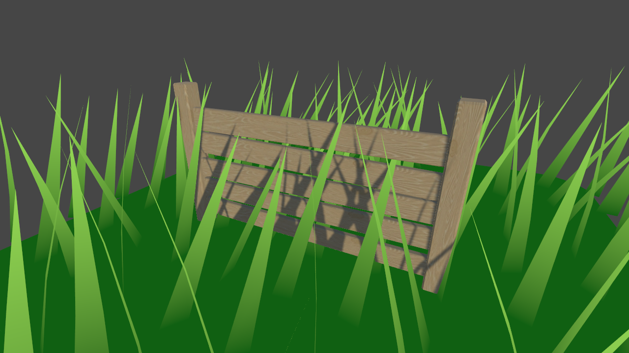
7.2 Receiving shadows
After Unity renders a shadow map from the perspective of a shadow casting light, it will run a pass "collecting" the shadows into a screen space texture. To sample this texture, we'll need to calculate the screen space positions of our vertices, and pass them into the fragment shader.
// Add to the geometryOutput struct.
unityShadowCoord4 _ShadowCoord : TEXCOORD1;

…

// Add to the VertexOutput function, just above the return call.
o._ShadowCoord = ComputeScreenPos(o.pos);
In the ForwardBase pass's fragment shader, we can use a macro to retrieve a float value representing whether the surface is in shadows or not. This value is in the 0...1 range, where 0 is fully shadowed, and 1 fully illuminated.
// Add to the ForwardBase pass's fragment shader, replacing the existing return call.
return SHADOW_ATTENUATION(i);

return lerp(_BottomColor, _TopColor, i.uv.y);
Finally, we need to ensure our shader is correctly configured to receive shadows. To do this, we will add a preprocessor directive to the ForwardBase pass to compile all necessary shader variants.
// Add to the ForwardBase pass's preprocessor directives, below #pragma target 4.6.
#pragma multi_compile_fwdbase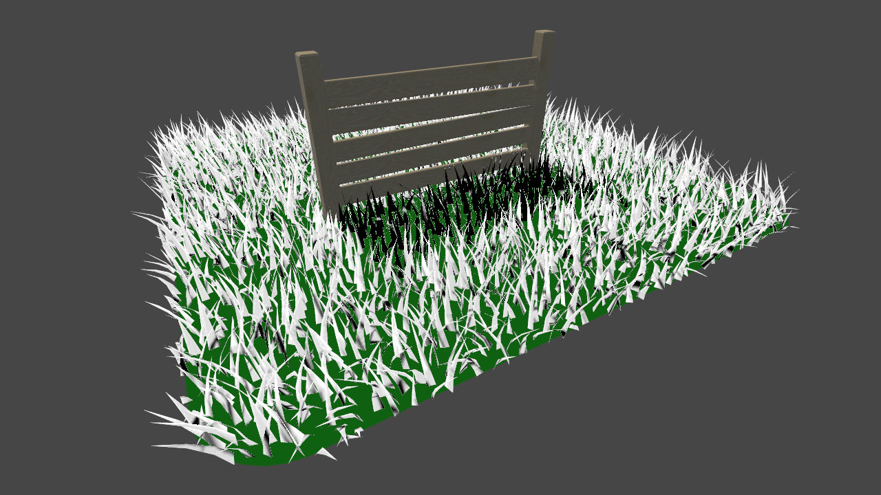
Zooming in, we can see some artifacts on the surface of the blades; this is caused by individual blades casting shadows on themselves. We can correct this by applying linear bias, or translating the clip space positions of the vertices slightly away from the screen. We will use a Unity macro for this, and include it in an #if statement to ensure the operation is only run during the shadow pass.
// Add at the end of the VertexOutput function, just above the return call.
#if UNITY_PASS_SHADOWCASTER
	// Applying the bias prevents artifacts from appearing on the surface.
	o.pos = UnityApplyLinearShadowBias(o.pos);
#endif
7.3 Lighting
We will implement lighting using the following common, very simple algorithm to calculate diffuse illumination.

...where N is the normal of the surface, L is the normalized direction of the main directional light, and I is the calculated illumination. We will not implement specular lighting in this tutorial.
Right now, the vertices in our blades of grass do not have any normals assigned. Just like we did for the positions of the vertices, we will first calculate the normals in tangent space, and then transform them to local.
When the Blade Curvature Amount is set to 1, the blades of grass all face the same direction in tangent space: directly backwards on the Y axis. As a first pass on our solution, we'll calculate the normal assuming no curvature.
// Add to the GenerateGrassVertex function, belowing the line declaring tangentPoint.
float3 tangentNormal = float3(0, -1, 0);
float3 localNormal = mul(transformMatrix, tangentNormal);
The tangentNormal, defined as directly backwards on the Y axis, is transformed by the same matrix we used to convert our tangent points to local space. We can now pass this through to the VertexOutput function, and then to the geometryOutput structure.
// Modify the return call in GenerateGrassVertex. return VertexOutput(localPosition, uv,localNormal); … // Add to the geometryOutput struct. float3 normal : NORMAL; … // Modify the existing function signature. geometryOutput VertexOutput(float3 pos, float2 uv,float3 normal) … // Add to the VertexOutput function to pass the normal through to the fragment shader. o.normal = UnityObjectToWorldNormal(normal);
Note that we transform the normal to world space before we output it; Unity surfaces the main directional light's direction to shaders in world space, making this transformation necessary.
We can now visualize the normals in our ForwardBase fragment shader to verify our work.
// Add to the ForwardBase fragment shader.
float3 normal = facing > 0 ? i.normal : -i.normal;

return float4(normal * 0.5 + 0.5, 1);

// Remove the existing return call.
return SHADOW_ATTENUATION(i);
Because our shader has Cull set to Off, both sides of the blade of grass are rendered. To ensure the normal is facing the correct direction, we make use of the optional VFACE parameter we have included in the fragment shader.
The fixed facing argument will return a positive number if we are viewing the front of the surface, and a negative if we are viewing the back. We use it above to invert the normal when necessary.

When Blade Curvature Amount is greater than 1, each vertex will have its tangent Z position offset by the forward amount passed in to the GenerateGrassVertex function. We'll use this value to proportionally scale the Z axis of our normals.
// Modify the existing line in GenerateGrassVertex. float3 tangentNormal =normalize(float3(0, -1, forward));
Lastly, we'll add some code to the fragment shader to put shadows, directional light, and ambient light all together. For a more detailed look at implementing custom lighting in shaders, I would recommend taking a look at my toon shader tutorial.
// Add to the ForwardBase fragment shader, below the line declaring float3 normal.
float shadow = SHADOW_ATTENUATION(i);
float NdotL = saturate(saturate(dot(normal, _WorldSpaceLightPos0)) + _TranslucentGain) * shadow;

float3 ambient = ShadeSH9(float4(normal, 1));
float4 lightIntensity = NdotL * _LightColor0 + float4(ambient, 1);
float4 col = lerp(_BottomColor, _TopColor * lightIntensity, i.uv.y);

return col;

// Remove the existing return call.
return float4(normal * 0.5 + 0.5, 1);
Conclusion
In this tutorial, the grass covers a small 10x10 area. To extend this shader to cover vast, open fields, some optimizations would likely be necessary to keep it performant. Distance-based tessellation could be used to have fewer blades of grass drawn further from the camera. As well, at further distances, instead of drawing each blade individually, clumps of grass could be drawn using a single quad that is texture mapped.
For improving on or extending the lighting and shading, while it is not natively possible to use geometry shaders with surface shaders, if it's desirable to use Unity's standard lighting model, this GitHub repository demonstrates a workaround by using deferred rendering and manually filling the G-Buffers.
View sourceAd. Interaction
Without interaction, graphical effects can feel static or hollow to players. As this tutorial is already very long, I abstained from including a section about how to have objects in the world interact with and influence the grass.
Naïvely, an implementation for interactable grass would contain two components: something in the game world that is capable of passing data into the shader to tell it what part of the grass is being interacted with, and some code in the shader to interpret that data.
An example of how to do this with water can be found here. This could be adapted to work with grass; instead of drawing ripples where the character is, the blades of grass could be rotated downward to simulate the footstep impacts.
Leave me a message
You can contact me about this article at Copied to clipboardroystanhonks@gmail.com 📋 roystanhonks@gmail.com 📧 . Sometimes I receive a lot of messages, but I'll try and get back to you as soon as I can!